Status
The status module displays the status of other avionics subsystems.
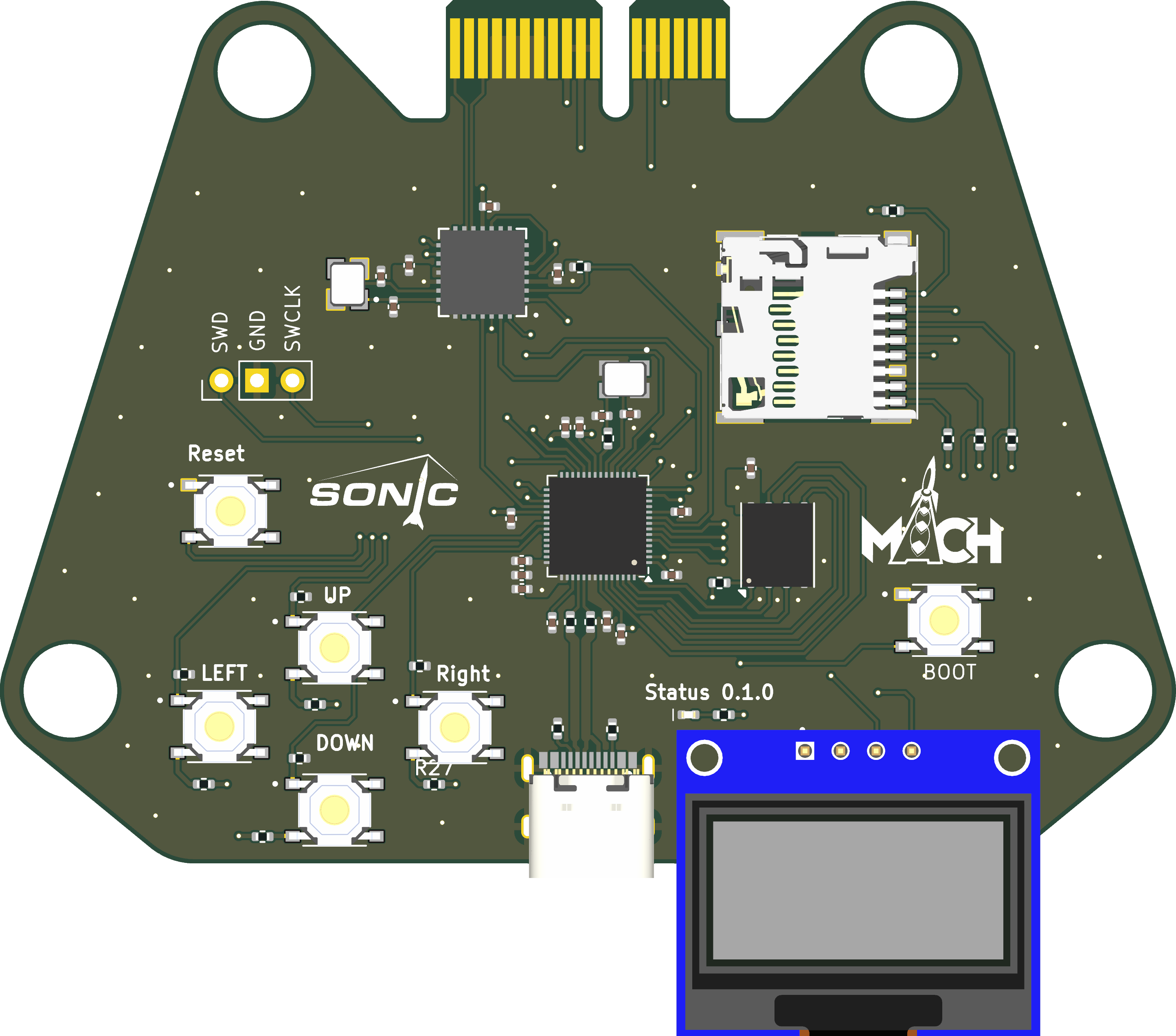
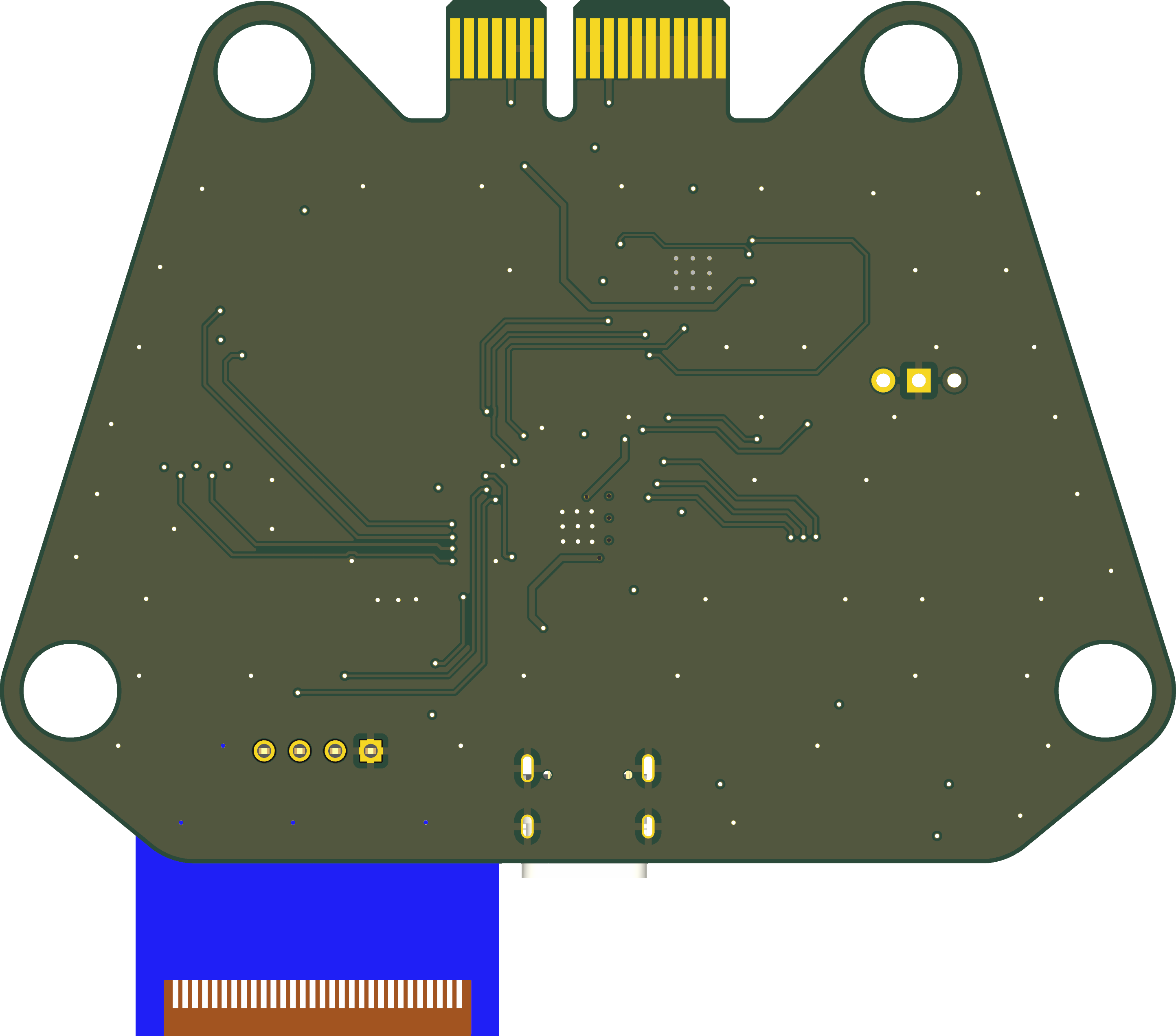
3D Render

Schematic
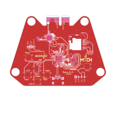
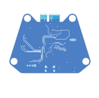
Footprint
Action Items
Schematic
- USB resistors
- Add buttons
- 4 LCD
- 1 reset
- 1 boot
- Source SD card mount
Routing
- Routing USB and CAN
- Learn differential pairs
- Learn about impedance matching
- Digikey trace width calculator
Testing
- Test out display module.
Components
MCP25625 CAN Controller
- The CAN controller reads messages from different modules and transmits the received data to the RP2040 MCU.
RP2040 MCU
- Receives CAN messages and displays them on an LCD screen.
- Push buttons connected to the MCU will be used for resetting and booting the MCU.
- Push buttons connected to the MCU will allow navigation through the CAN messages displayed on the LCD screen, enabling switching between different devices forward and backward.
Micro SD Card Slot
- Capable of storing CAN data onto an SD card.